 Strata Design Journal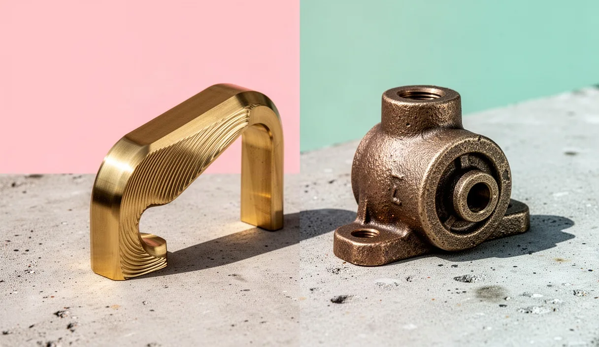

Architectural hardware projects demand a choice between subtractive machining and near-net-shape casting early in the design phase. For production volumes spanning a single bespoke entryway handle up to several hundred matching sets for a boutique commercial interior, the selection dictates not only the final surface character but also the production schedule, tooling liability, and unit cost. Selecting the wrong path early results in either massive material waste from aggressive roughing operations or high scrap rates caused by casting defects in thin cross-sections.
CNC milling carves the final profile directly out of wrought billet, extruded bar, or plate stock. Sand casting pours molten alloy into bonded sand molds formed around reusable patterns. While 5-axis milling provides geometric freedom, immediate turnaround, and sub-millimeter precision, sand casting handles organic curvature, volumetric mass, and complex undercuts with lower raw material consumption. Deciding between them requires balancing scrap rates, structural grain structure, raw material costs, and the visual vocabulary demanded by the architectural specification.
Unit Economics: Tooling Setup Versus Billet Waste
The financial crossover between CNC milling and sand casting hinges on the relationship between initial tooling expenditure and per-unit cycle time. Milling involves almost zero dedicated tooling costs outside of custom soft jaws or modular fixturing plates. The machine code can run immediately once programmed. However, when machining an organic door pull with deep offsets from a solid rectangular billet of C63000 nickel aluminum bronze, material removal rates can exceed 78 percent of the initial block weight. The client pays for metal that exits the machine enclosure as chips, which fetch only a fraction of their purchase value at the scrap yard.
Sand casting shifts the capital expense to pattern equipment and core boxes. A matchplate pattern milled from high-density polyurethane tooling board or aluminum costs between $1,800 and $6,500 depending on geometry and parting complexity. Once the foundry rigs this pattern, the consumable cost per casting remains low: the mold uses bonded silica or olivine sand that is reconditioned, and runners and risers are remelted in-house. When amortized across 20 units, pattern tooling adds a severe markup; spread across 350 units, the pattern cost drops to a negligible line item while saving substantial metal mass compared to subtractive cutting.
| Production Factor | 5-Axis CNC Milling | Sand Casting (Green or Resin Sand) |
|---|---|---|
| Upfront Tooling Cost | $250 to $800 (Soft jaws, custom holding fixtures) | $1,800 to $6,500 (Matchplates, core boxes) |
| Material Utilization | 18% to 45% (Remainder converted to chips) | 82% to 92% (Gating trimmed and remelted) |
| Economic Batch Break-Even | 1 to 35 units | 40 units and above |
| Cycle Time per Unit | 45 to 180 minutes spindle time | 8 to 22 minutes (Molding, pour, shakeout) |
Consider a run of 45 custom bronze door pulls measuring 450 mm in length with a compound sweeping grip. Roughing and finishing this geometry on a 5-axis mill requires approximately 110 minutes per piece, generating 8.4 kg of bronze chips per unit. A sand foundry can pack molds, pour, shake out, and cut off gates for the same run in two shift days once the pattern is delivered. For runs beneath 25 units, the programming time and billet cost of milling remain cheaper than paying patternmakers. Above 40 units, the low material waste and swift cycle time of casting balance out the initial pattern tooling.
Tolerances and Geometric Constraints of 5-Axis Milling
Milling hardware components on a continuous 5-axis machining center delivers dimensional accuracy that casting cannot match without post-machining. Typical linear tolerances hold within plus or minus 0.025 mm across a 300 mm span, with bore concentricity for lock cylinders and pivot bearings maintained within 0.012 mm. This level of repeatability guarantees that mechanical components, such as mortise cassettes, latches, and internal return springs, mate directly to the architectural trim without secondary hand-fitting or reaming on site.
The primary constraint in 5-axis milling is tool reach, deflection, and collision envelopes. Deep, narrow pockets or dramatic organic undercuts require long-reach end mills. As the ratio of tool length to cutter diameter exceeds 4:1, tool chatter increases dramatically, necessitating lower feeds, conservative depths of cut, and repeated passes. A pocket 120 mm deep requiring an internal fillet radius of 2 mm forces the use of a tapered ball-nose tool that adds substantial machine time to prevent tool breakage. Deep internal chambers that loop back on themselves cannot be milled from a single solid block unless the component is designed as a split assembly joined with mechanical fasteners or continuous electron-beam welding.
Surface generation also differs fundamentally from cast textures. 5-axis milling paths generate scallop marks governed by the step-over distance of the ball-nose or bull-nose cutter. To achieve a surface finish ready for immediate chemical patination or light abrasive buffing (around Ra 0.8 micrometers), the step-over must be held below 0.15 mm. This tight spacing extends cycle times. Machinists must balance cycle economics against subsequent bench labor: running faster machining toolpaths leaves heavier tool marks that an artisan must sand out manually, risking dimensional drift on sharp design edges.
Draft Angles, Shrinkage, and Parting Lines in Sand Casting
Sand casting relies on packing bonded sand around a rigid pattern, splitting the mold flask, and pulling the pattern out without collapsing the sand cavity. This operational reality demands draft angles on all vertical faces parallel to the draw direction. For hand-rammed green sand molds, a minimum draft angle of 2.0 degrees is recommended; automated no-bake resin sand molds can often pull clean walls with 1.0 to 1.5 degrees of draft. Attempting to cast zero-draft vertical surfaces causes the sand to tear away during pattern removal, leaving inclusions, rough steps, and dimensional blowouts on the finished hardware.
Shrinkage must be calculated into the pattern design from the start. As molten metal cools from liquidus to room temperature, the volumetric contraction alters every dimension. The patternmaker must scale the pattern dimensions up using alloy-specific shrink rules:
- Silicon Bronze (C87600): expands patterns by approximately 1.56 percent (3/16 inch per foot).
- Austenitic Stainless Steel (CF8M/316 equivalent): expands patterns by 2.08 to 2.60 percent (1/4 to 5/16 inch per foot).
- Architectural Aluminum (A356): expands patterns by approximately 1.30 percent (5/32 inch per foot).
Unequal wall thicknesses amplify shrinkage problems. If a bespoke door lever transitions abruptly from a thick 35 mm structural boss to a slender 6 mm decorative grip, the thinner section solidifies first, choking off the molten feed metal to the thicker hub. The result is internal shrinkage porosity or external sink marks. Foundry engineers mitigate this by incorporating feeding risers or using internal chills, but the hardware designer must design smooth transitions with blending radii of at least 3 mm to maintain metallurgical density.
The mold split leaves an indelible feature: the parting line. This line marks where the cope (upper mold) and drag (lower mold) meet. Sand casting patterns inevitably have flash along this seam, which must be ground flat, blended, and re-textured. If the parting line cuts directly across a focal aesthetic surface, such as the face of an architectural escutcheon, the manual blending will show variation across a production lot. Orienting the parting line along natural structural edges or hiding it on the unexposed rear surface preserves the visual integrity of the design.
Secondary Finishing: Vibratory Tumbling, Blasting, and Polishing
Neither a freshly milled billet nor an as-cast hardware component is ready for installation out of the machine or sand mold. Secondary finishing converts raw surfaces into tactile, uniform architectural hardware. The sequence of finishing steps differs based on the starting material condition.
Surface Preparation Process
- Substrate Cleaning and Gate Removal: For castings, slice away pouring sprues, risers, and parting flash using a horizontal band saw or water-cooled cutoff wheel. Grind the stub flush with a 60-grit zirconia belt. For milled parts, wash away water-soluble coolant residues in an ultrasonic bath using an alkaline cleaner at 60 degrees Celsius to prevent staining.
- Mass Finishing and Radiusing: Place parts into a vibratory tub or centrifugal disc finisher. To remove cutter scallops from CNC parts, run medium-density ceramic cones with a light cutting compound for 140 minutes. For sand castings, use fast-cutting synthetic triangular media to knock down surface roughness from sand grains (reducing Ra from 12.5 down to 3.2 micrometers) without softening critical registration edges.
- Abrasive Media Blasting: Blast surfaces using clean virgin aluminum oxide (120-grit) at 0.45 MPa of pressure to achieve a uniform matte industrial finish. If a satin pearlescent sheen is desired on stainless steel or bronze, switch to spherical soda-lime glass beads (size range 70 to 140 mesh) at 0.28 MPa to peen the surface without cutting into it.
- Stage Mechanical Polishing: Progress through abrasive belts from 180-grit to 320-grit, followed by 400-grit silicon carbide greased compounds. Final mirror finishes require sisal buffs charged with fast-cut compound, followed by loose-leaf cotton wheels running at 1,800 surface meters per minute treated with dry rouge.
Castings require substantially more hand polishing labor to eliminate micro-porosity and sand burn-in, which sit just below the cast skin. If an architectural specification calls for an unlacquered, high-mirror optical polish, CNC milling provides a denser, pore-free substrate that reaches a defect-free shine in roughly half the polishing time of a sand casting.
Specifying Metal Grades for Outdoor Architectural Hardware
Outdoor architectural hardware faces atmospheric corrosion, ultraviolet exposure, salt spray, and physical abuse. Specifiers must choose alloys that resist degradation while performing well within the chosen production method.
For CNC machining from solid stock, silicon bronze C65500 and architectural bronze C38500 are common, but they behave differently. C38500 contains lead to facilitate clean chip-breaking and rapid machining speeds, but its zinc content leaves it susceptible to dezincification in marine exterior environments, yielding a pinkish, brittle surface over time. C65500 contains roughly 3 percent silicon and less than 1.5 percent zinc, offering superior resistance to coastal chlorides and weathering to a rich statuary patina. For stainless parts, wrought AISI 316L provides exceptional pitting resistance due to its 2.0 to 2.5 percent molybdenum content, machining cleanly when using rigid carbide tooling with positive rake geometries.
For sand casting, the equivalent alloys carry different chemical designations and metallurgical behaviors. Silicon brass/bronze C87600 is an exceptional casting alloy, running with high fluidity at 1,020 to 1,080 degrees Celsius, reproducing intricate mold details cleanly while offering high tensile strength (approaching 450 MPa). If specifying stainless steel hardware for outdoor coastal use, call for ASTM A743 Grade CF8M (the cast variant of 316). CF8M contains between 8 and 21 percent ferrite in an austenitic matrix to prevent hot cracking during solidification. However, this residual ferrite can cause very light surface magnetic attraction, which occasionally alarms clients who expect cast stainless to be completely non-magnetic.
| Alloy Specification | Method Suitability | Corrosion Resistance Class | Tensile Strength (MPa) | Machinability / Fluidity Rating |
|---|---|---|---|---|
| C65500 High-Silicon Bronze | 5-Axis CNC Milling | Marine / Severe Exterior | 400 | Machinability Index: 30 |
| C87600 Cast Silicon Bronze | Sand Casting | Marine / Severe Exterior | 450 | Fluidity: Exceptional |
| AISI 316L Stainless Steel | 5-Axis CNC Milling | Marine / Industrial Urban | 485 | Machinability Index: 45 |
| ASTM A743 CF8M Stainless | Sand Casting | Marine / Industrial Urban | 485 | Fluidity: Moderate |
| C38500 Architectural Bronze | CNC (Extruded Bar) | Protected Exterior / Interior | 410 | Machinability Index: 90 |
Common Mistakes in Hardware Production
The most pervasive error in specifying milled hardware is modeling sharp internal corners that match external edges. CNC end mills are circular cylinders; they cannot carve an internal square corner inside a pocket. Forcing sharp inside corners requires secondary sinker electrical discharge machining (EDM) or broaching operations that drastically inflate unit costs. Designers should radius all internal corners to a dimension slightly larger than standard tool radii (for example, specifying a 3.5 mm radius rather than a 3.175 mm radius for a 6.35 mm tool) to prevent cutter binding in the corners.
For sand casting, the most common oversight is neglecting core support and thermal balances. Specifiers frequently draw solid thick sections joined directly to gossamer-thin structural flanges without providing adequate draft for pattern extraction. This generates sand drag, producing inclusion defects throughout the finished lot. Another failure is failing to specify an allowance for post-cast machining on functional mating faces. Hardware components require cast stock allowances of at least 2.5 mm on all surfaces that will be milled or tapped later, accommodating for pattern shift and decarburization layers.
A cross-process mistake involves patination expectations. When combining CNC machined components and cast components on the same door assembly, such as a milled escutcheon plate combined with a sand-cast handle, using identical chemical patina baths will yield different colors. The wrought plate has an oriented, compressed grain structure, whereas the casting exhibits a dendritic crystal structure with varying surface porosity. The cast part absorbs the patina chemicals faster and deeper, resulting in mismatched tones unless finishing formulas are adjusted by an experienced metal finisher.
Practical Next Steps for Specifiers
Move the hardware design out of conceptual rendering software and into a manufacturing evaluation pipeline:
- Audit the Volumetric Ratio: Calculate the volume of the finished part against its minimum bounding box. If the component utilizes less than 28 percent of the block volume and the order quantity exceeds 35 pieces, immediately contact a foundry for pattern quoting instead of defaulting to subtractive machining.
- Conduct a Machine Tool Reach Study: If 5-axis milling is the preferred path, run continuous toolpath collision simulations. Check for features that mandate cutter reach-to-diameter ratios beyond 5:1. If found, split the component into two mechanically registered pieces or widen the internal radii.
- Build a Physical Rapid Pattern: Before cutting metal tooling for casting, 3D print the proposed part using stereolithography (SLA) or selective laser sintering (SLS) at full scale. Test the hand grip ergonomically, inspect the line of sight for parting seams, and verify that mechanical clearances align with the intended mortise lock assemblies.
- Contract Specialized Metallurgical Verification: When hardware must fulfill load-bearing duties, such as heavy exterior pivot assemblies or structural glass patch fittings, obtain material test reports (MTRs) for raw billets, or commission non-destructive testing (radiographic or dye penetrant inspection) on initial sample castings. Consult a licensed structural or materials engineer to confirm that selected cast sections will withstand designated wind loads and cyclical operational fatigue.